Codes and Standards: Salt Lake City???s City Creek Center
Words: Dan Kamys
Codes and Standards
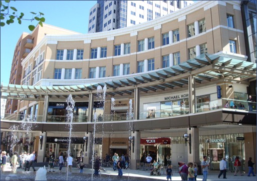
While the economic conditions of these last five years have crippled most cities, the timing of City Creek Center has been like manna to the people of Salt Lake City. The Downtown center resembled a hive of bees as 1,100 construction workers toiled on a 23-acre site – more than three city blocks – adjacent to the Mormon Temple. A unique and stringent set of codes and standards had to be met during the transformation of the old Crossroads mall into a vibrant, new mixed-use area.
By Jeff Elder, SE, LEED AP BD+C
In 2003, leaders of the Church of Jesus Christ of Latter Day Saints (LDS) purchased the Crossroads mall, following years of declining sales and after Nordstrom, a major tenant, threatened to leave. The decision was made to redevelop the area adjacent to Temple Square and keep it economically and culturally vibrant.
Many of City Creek Center’s design decisions hinged on whether to tear down two malls constructed in the 1970s and several old buildings adjacent to the mall, or to upgrade the mall to newer seismic code requirements. Retrofitting the existing buildings would be too costly, so a new master plan was developed and extensive design teams and consultants were brought on board.

Taubman, a mall management company, along with seven architectural firms, three general contractors and 50 consultants, joined the project team to find a way to revitalize the core of the city. City Creek’s answer was a $1.2 billion regeneration of downtown Salt Lake City through a walkable, sustainably designed, urban community of retail stores, offices and residences. In October 2006, the LDS church announced plans for development of City Creek Center. Demolition started shortly thereafter, and all demolition was complete by the end of 2007.
The project
Surrounding architecture would set the style and the standard for the new center, as well as for the selection of exterior facing materials. Bricks and stones were selected for their aesthetic tie to adjacent buildings and for their durability. To tie to adjacent architecture, the bricks were required to match the 2.25- X 7 5/8-inch face dimension and be of similar texture and color.
The building envelop design was further complicated by the need for 100-year life materials in every layer of the wall. This included bricks, wall ties, insulation, an air and vapor barrier, and studs. It was critical to the overall success of the building envelop that thermal bridging and wall tie penetrations be eliminated or drastically reduced.
 Curtain Wall Detail
In addition to the material specifications, several requirements had to be met. The first challenge was to provide a design that would comply with the high seismic requirements of a building located in downtown Salt Lake City. Rigid masonry materials had to comply with the ductile, drift requirements of multistory buildings. Earthquake design dictated that each heavy, articulated precast concrete panel would be incorporated into the brick wall, which would require unique support conditions.
Because of the complexity of the wall envelop, the bricks were designed as structural brick veneer (SBV). SBV essentially is the same as conventional brick veneer, except it is reinforced. Hollow bricks conforming to ASTM C652 specifications generally are selected, so there is sufficient cell space to allow for reinforcing and grout.
Structural Brick Veneer
The brick coring is larger and configured so that the cells align and can be reinforced when placed in the wall bond pattern. Reinforcement increases the structural capacity of the brick wall. This allows the spacing of wall ties to be increased to distances between floors and columns. Thus, conventional veneer ties are eliminated and replaced by more substantial connectors.
The Wall System
The original design looked at eight-inch-long bricks in various widths, but this concept was labor intensive. To reduce labor costs, specially designed 16-inch-long structural bricks with special coring and slotting were developed, to capture the architectural charm dictated by the face size.
City Creek Center elected to use a structural brick rainscreen curtain wall, comprised of 6- X 2.25- X 16-inch and 8- X 2.25- X 16-inch Atlas bricks. In some conditions, heavy precast concrete panels hung from the bricks. In others, the precast concrete was supported by the structural brick. Be sure these prior two sentences are correct – it was a run-on sentence, I think, so I separated into two.
A single brick with different slotting on the front and back of the unit further reduced the number of different bricks on the project. This had a significant effect on reducing labor costs. In the detail to the right, a 16-inch column was constructed by flipping the front and back sides of the same unit, to give a two- or three-brick appearance.
Various thicknesses of structural bricks were used to support the heavy precast concrete pieces hung from the brick, and to withstand the high seismic forces dictated by seismic Category D code requirements.
 Solution – Reinforceable 8x16 Slotted
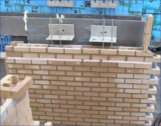
The structural brick veneer system was designed like a precast concrete wall panel. The bricks became the form for the grout and reinforcing. By using structural bricks, the panels could be constructed in place, which eliminated added costs in freight, labor and handling. Each wall was built as a panel separated by vertical and horizontal expansion joints. Although built in place, each panel was connected to four heavy, galvanized steel plate connectors that carry the vertical and lateral wall loads. Connectors similar to precast panel connectors are designed with allowances for in-plane vertical and lateral expansion, contraction and deflection.
Light-gage studs could be used behind the bricks to support the sheathing, as they were not required to transfer wind or earthquake loads from the bricks.
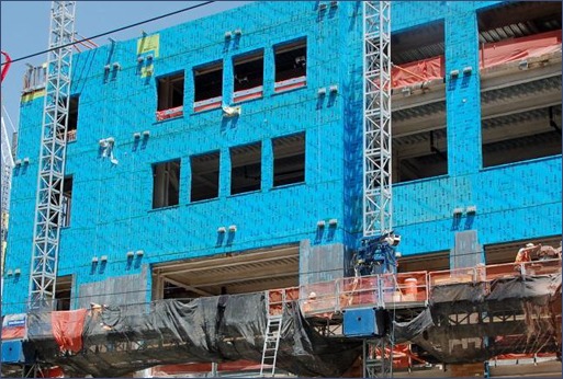
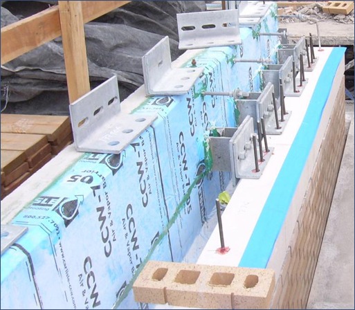
Typical brick veneer wall ties spaced at 16 inches on-center in each direction were eliminated. Less-frequently placed, larger heavy-steel connections were used. A continuous layer of insulation (uninterrupted by wall ties) was placed behind the bricks. The reinforced structural brick curtain wall was then installed and connected to four strategically placed rigid connectors as shown in the photograph below.
This system reduces the number of penetrations in the moisture, vapor and air barrier caused by frequent wall ties. The reduction in wall ties reduces the thermal conductance of energy through the insulation layer.
A one-inch-thick layer of insulation was placed between brick panels at each window head to isolate floors. The insulation acted like a lintel, by providing support to the bricks during construction prior to the final curing of the grout. The insulation also formed the separation between floors to accommodate seismic drift.
Return to Table of Contents