September 2015
Anchors, Connectors and Fasteners
By Paul Curtis
I have been around masonry anchors my entire life. My grandfather started our anchor manufacturing business 92 years ago. Having been involved full-time in this business for the last 36 years, I have witnessed the creation of many extraordinary masonry buildings. I have also been called upon to give my opinions on many problem buildings. Over the years, I have received photos from inspectors and building owners asking about some anchor installations that seemed questionable.
Masonry building construction is a combination of three groups: designers, product manufacturers and installers.
The designers (architects/engineers) will choose the products to use in their buildings based on the structural characteristics of those products. Any deviations of the products chosen need to go through the “change order” procedure, whereby the designers make the final decision.
The product manufacturers have an array of anchoring systems available for the designers to specify.
The installers will purchase the anchors either from the manufacturers or through their distributors.
- Common problems
Contractors grab what they have on their trucks and use it
If it doesn’t fit, make it fit
It’s buried in the wall, nobody will see it
I have the wrong anchors, but we need to get this wall up today
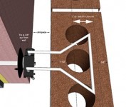
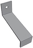
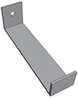
Physics: Masonry anchors transfer lateral loads between the veneer and the backup. These anchors should transfer 400 pounds of tension and compression (100 pounds required with a safety factor of 4). When using an adjustable system, the two anchors cannot be more than 1 ¼-inch out of plane. Installers must be aware of this requirement. Standard wire tie configurations have been tested for their capacities. Below are some situations where incorrect anchor lengths were “modified” on the jobsite. All of these modifications below can cause life safety issues. If it doesn’t fit, get the right anchors!
|
|
|

Airspaces: I am a big supporter of two-inch airspaces. The TMS 402 Code requires a minimum one-inch airspace. If you specify a one-inch airspace, then there is zero tolerance for error. I’ve seen buildings where the structure and building envelope are built, and the mason is left with a half-inch airspace. This is due to minor variances over the length of the walls. Specifying a two-inch airspace will help with minor tolerance issues.
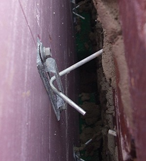
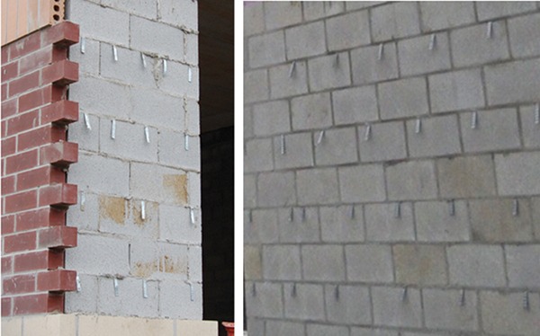
Corrugated Wall Ties: These are probably the most abused anchors in our industry. They are also the least expensive and are often substituted at the jobsite without approval. They can only be used in wood backup construction with a maximum one-inch airspace. I see walls like these all over the country. Corrugated wall ties cannot be used with CMU backups. They are not up to code!
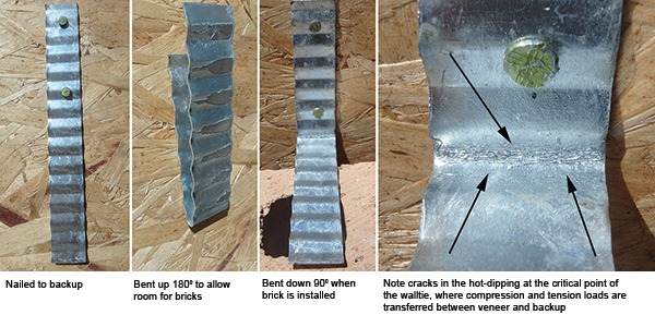
The code requires exterior wall anchors to be either hot-dip galvanized after fabrication or stainless steel. The problem with corrugated wall ties is the hot-dip galvanized after fabrication. These anchors are screwed or nailed to the backup, bent up 180⁰ to allow the bricks to be laid, and then bent down 90⁰ to fit in the mortar joint. In essence, they are being fabricated in the field by bending that sometimes cracks the hot-dip galvanizing at the critical point where compression and tension loads are transferred between the veneer and the backup. My recommendation for corrugated wall ties is to specify stainless steel.
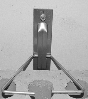
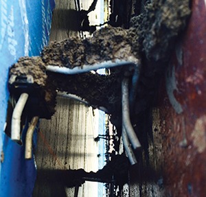
Stone Anchors: Stone veneers need to have the anchors engineered. I cannot tell you how many times we have received a call from the jobsite: Stone is delivered and ready for installation, we need anchors in two days. They don’t know what anchors or how many, but they need to get the stone up.
 |
 |
 |
 |
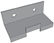 |
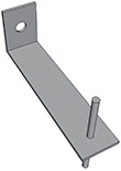
Figure 6. Stone Anchors
The stone needs to be analyzed to determine the anchor placement for even distribution of the loads. The backup needs to be analyzed to determine how and where the structure will receive these loads. Finally, the anchors are designed to transfer these loads effectively. The stone and the distance from the backup will require the anchor to be a certain length. The anchor is strengthened by increasing the thickness, width and attachment considerations to the backup. I’ve seen jobs go on hold for several weeks while the engineering is performed and the anchors manufactured. There have been situations where, through the analysis, the stone doesn’t meet the criteria, because it is too thin and everyone ends up scrambling for solutions while the job is on hold.
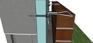
3/16-inch diameter wire spans the entire 6-inch cavity
Stone anchor engineering needs to be considered long before the stone arrives at the jobsite. I have seen cases where the engineering has been performed by the structural engineer on the project, the stone manufacturer, or was the responsibility of the mason contractor. If the anchors are not engineered by the designers then the responsibility should be spelled out before the project goes to bid. Projects have been held up while everyone fights over who will pay for the engineering.
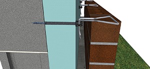
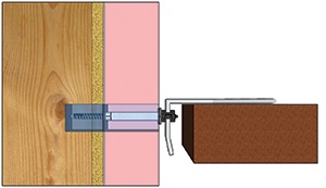
Large diameter barrel screw goes through the 4-inch insulation
3/16-inch diameter wire tie spans 1 ¾ inch of the airspace
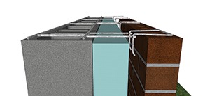
Cavities Over 4.5 Inches: The TMS 402 Code states that anchors must be engineered when the distance between the backup and the inside of the brick exceeds 4.5 inches. With Continuous Insulation (CI) and the new energy codes, this situation occurs quite often. Using barrel screw anchors helps to alleviate the problem of anchoring veneers with wide cavities. Wire ties in a mortar joint cannot be more than half the thickness of the joint. For a 3/8-inch diameter joint, the wire tie cannot exceed 3/16-inch. Barrel screws on the market typically have a diameter ranging from 5/16- to 3/8-inch. If you have 2.5 inches of sheathing and a two-inch airspace you are within the 4.5-inch range. The 3/16-inch wire tie typically spans 1 ¾ inch of that airspace.
Large diameter barrel screw goes through the 2-inch insulation
3/16-inch diameter wire tie spans 1 ¾ inch of the airspace
Compression loads on the wire tie cause the anchor to fail around 1,400 pounds. This failure is caused by the wire tie blowing out of the mortar joint or the wire tie buckling. If you have a cavity that has 4.5 inches of insulation and two inches of airspace you will need to engineer the anchoring systems. The barrel screw will now be 4.5 inches, and the wire tie will still only span the 1 ¾ inch in the airspace. Compression failure will be the same as the 4.5-inch cavity, because the 3/16-inch diameter wire tie is spanning the same sized airspace. When using wire reinforcement, the compression loads on the 3/16-inch diameter wire span the entire 6.5-inch cavity and will be greatly reduced.
BIA Technical Note 44B: The Brick Industry Association Technical Note 44B recommends specifying ties with maximum deflections of less than 0.05 inch, when tested at an axial load of 100 pounds in tension or compression. This is often written in specifications as a requirement for adjustable anchors. Tech Note 44B also states that the maximum play in the connection between the pintle and the anchor is 1/16-inch, which is part of the TMS402 Code.
|
|
|

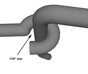
The 0.05-inch maximum deflection is a recommendation only. It is not a part of the code. If you have a 1/16-inch space between the pintle and the eye, you can move the pintle back and forth with a few pounds of pressure. One-sixteenth inch is 0.0625 inch, which is 0.0125 inch over the recommended 0.05 inch for 100 pounds. If you write the 0.05-inch deflection in your specification, then no adjustable anchor will technically comply. Once the pintle is up against the eye, you will meet the 0.05-inch maximum deflection for the first 100 pounds with 3/16-inch pintles and eyes.
Those of us in the masonry business want to see quality buildings built that will last lifetimes. It is critical that we all work together to achieve this goal.
Paul Curtis is a voting member on two committees of the MSJC TMS402 Building Code and president/owner of Heckmann Building Products Inc.
Product to WatchDissipative Anchor From Cintec |
|