
Flashing & Drainage
The Role of Flashing in Masonry

We tend to think of bricks, blocks and mortar as some of the most durable building materials ever known to man. Throughout history, monuments, public facilities, and even our homes have been made with one form of masonry or another. Ironically, as we continue to develop new products and building methods, we race to find suitable methods to prevent or repair issues that arise with them.
Here’s food for thought: Why does the masonry on a university library built less than 10 years ago require almost as much money invested in its repair as it cost to initially erect it? At the same time, consider how a building like Somerset House in London, built somewhere around 1755, has survived all these years without the benefit of a weep system or mortar collection device in its construction.
I’m not suggesting, by any means, that we change the way we construct today’s brick veneer buildings. They are a far less expensive alternative to the old multi-wythe brick structures and, of course, much faster to build. Comparatively, brick veneer construction should also be much less prone to moisture damage, as it does not retain water the way a barrier wall structure may. As moisture migrates toward the inner wythes, it softens and weakens the mortar joints in the old construction, often leaving them to later crumble away. In brick veneer construction, while moisture still migrates inward, it is more easily managed, as we have the opportunity to collect, channel and redirect it – lessening the harmful effects indicative of moisture penetration.
 |
|
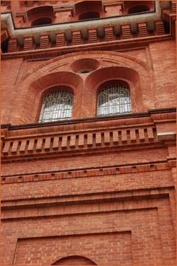
| Older architecture often incorporated corbels and recesses around its openings to keep moisture away from problematic areas. |
What I am suggesting, perhaps, is that we continually may be rushing ahead of ourselves. The prospect of holding a proprietary specification gives birth to new products and the methods of using them, with little regard to their long-term function or compatibility with other materials and systems. So many new products and corresponding information are thrust upon the construction community month after month, it has become impossible to keep up with it all. Inventors or manufacturers bring new products to designers and specifiers who, in turn, require them to be used in projects before the contractor knows the intricacies of their installations. Unfortunately, as many good products as bad are lost in this process.
Nothing is more damaging to masonry than moisture. In fact, it is suggested that 90 percent of all masonry issues are moisture related. Over time, water will work to break down masonry joints and, if unprotected for long periods, it will degrade the anchoring systems within the wall as well. Prolonged exposure of moisture inside the wall will fuel a bloom of mold, efflorescence, or calcium encrustations, in some cases scarring the wall’s face permanently.
In comparing old construction to new, the methods of moisture control differ significantly. Old construction uses ornate construction details like corbels and recesses to shed rainwater away from its fa??ade. Newer, modern design incorporates less of these details and leaves the wall face much more susceptible to moisture penetration. The proper flashing materials, used correctly, are imperative to protecting the structures we build today.
Flashing’s function
First, let’s look at what a flashing does. While flashing certainly offers a line of defense to the interior wall as a barrier to infiltrating moisture, we should not think this to be its only purpose. A flashing material in cavity wall construction needs to act as a means to moisture collection, and then more importantly to the diversion of it. Understanding that moisture inevitably will become part of the equation in a veneer wall is also the key to protecting the structure in the long term.
The quality of the flashings we use (a characteristic I find we ignore far too often) correlates directly and is crucial to the permanence of the wall. Synthetic membranes, peel-and-stick flashings, and all-in-one flashing systems that utilize synthetic membranes should never be confused with permanent moisture protection. Simply checking the manufacturer’s warranty should give you a good idea of how long to expect the material to last.
Of all the materials I have had the opportunity to work with, a 5- or 7-ounce copper flashing still makes the most sense to use in all areas of the cavity wall. Its rigidity makes it self-supporting, yet they remain sufficiently flexible in the task of forming corners and end dams. Copper flashings exceed synthetics in puncture and tear resistance as well, assuring a stout collection area for any moisture pooling within the wall cavity.
As I said before, one of the most important steps to protecting a wall system from penetrating moisture is to acknowledge that it will likely be present. Let’s consider some of the more common ways moisture permeates something as solid as bricks and mortar.
Wind-driven rain
All masonry materials are actually quite porous. This porosity can be accentuated further in different types of brick, or in varying surface cracks and imperfections in the masonry units. What’s referred to as the “contact zone,” or the area where the mortar and the bricks actually meet, is in fact the most porous part of the wall face and where moisture is most likely to enter unless repelled. Considering that mortar makes up 18 percent of the wall face, the area this contact zone makes up is significant to say the least.
The combination of water volume and wind pressure in a heavy rainstorm is probably the most significant factor of moisture penetration in masonry construction. The walls will become saturated as the rain fills the masonry’s pores, cracks and imperfections. In this circumstance, water moves from concentrations higher to lower, more or less allowing the materials to “suck” the water right inside the wall. This is even more prominent in walls with thin and weak head joints. In older walls, in which freeze/thaw cycles have created spalling of the masonry joints, there is no resistance to water entering the wall cavity.
While the previous example shows why cracking on the wall face is a problem, I think it’s important to consider where they come from, so we see how likely they are to occur. Brick units, as we are all aware, expand significantly throughout their life cycle. Concrete masonry, on the other hand, shrinks significantly throughout its service life. Both of these issues need to be coped with independently, or the wall movement will produce considerable cracking on its surface. Along the same lines, mortar mixes may tend to act much like cement block. Particularly, if too much cement or too much water is added to the mix, you will most certainly see separation cracks in the joints, due to shrinkage. Cracks also are commonly caused by differential settlement under heavy loads, and in some cases, thermal expansion where the wall is not reinforced properly.
Thermal bridging
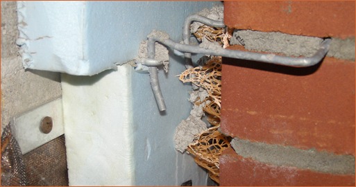
The “Moisture Control Handbook” defines thermal bridging as “regions of relatively high heat flow conductance in a building envelope.” A simpler definition would be a continuous path across a temperature difference, which we all know in extremes will cause condensation. In steel stud construction, consider the corner of a building with insufficient insulation. Cool, conditioned air from the inside of the building may be coming into contact with the much warmer air present in the wall cavity. In just a few months, you may have a significant problem on your hands.
Workmanship
I consider workmanship to be the most significant factor of moisture penetration in masonry that we can maintain complete control over. Taking care to properly install materials by following the manufacturer’s recommendations are pertinent details to good mason work. As noted earlier, attention to full mortar joints and correctly proportioned cement, sand and water in the mix also are major contributors to the longevity of the structure. The mortar joints also need to be tooled appropriately during construction, both to give the joints added strength and to provide the joints with a geometric shape conducive to shedding water. Good joint tooling reduces the permeability of the wall, period.
Now that we know some of the means by which moisture makes its way into the wall cavity, let’s look at how we redirect it.
I mentioned the importance of flashing materials earlier. While there is no alternate for a quality flashing material, its presence in the wall system is not enough. Every flashing detail helps to maintain its continuity and, when overlooked, will undoubtedly lead to a failure in the collection system. These details, once again, speak to workmanship during the construction process.
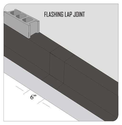
The first consideration of the flashing system is continuity, or having the least amount of laps and seams. This also differs from material to material. Consider, if you will, an eight-foot section of 260-gallon, stainless-steel base flashing. While, without question, it should last well beyond the life expectancy of the wall, does it alone provide a continuous means to collect moisture? On a span of just 60 feet, you would require eight lap joints to complete the flashing end to end. Some of the newer “all-in-one” flashing systems on the market at five-foot intervals would require 12 joints! Everywhere a joint or seam exists, so too does the opportunity for a failure in the wall. In a copper or peel-and-stick flashing, you would require only one across this same span, if any at all.
The laps themselves are extremely important, and inevitable on just about any wall. Laps should be a minimum of six inches, and sealed with the manufacturer’s recommended sealant or mastic. Mastics do, in fact, differ from one another, so compatibility is of tremendous concern, particularly when the membrane is synthetic. Some newer flashings, both copper and synthetics, allow for the use of urethane or silicone sealants, making installation much faster and cleaner.
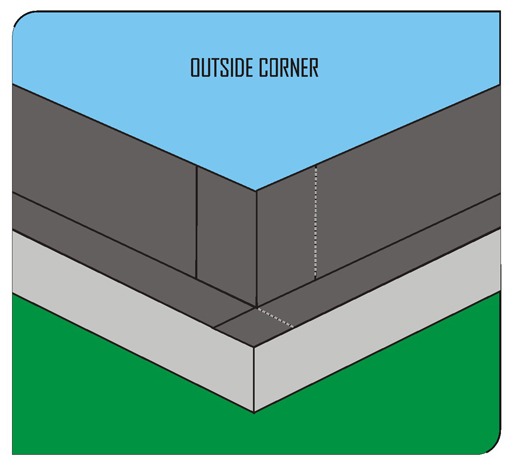
The corners of a wall or end dams at windows often are problem spots where moisture gets behind the flashing, either for lack of a good lap seam, or lack of one at all. The process of cutting, folding and seaming rolled flashings to form corners again correlates directly to the workmanship of the person installing it. Most flashing manufacturers offer premade corners or end dams in compatible materials to help alleviate this problem.
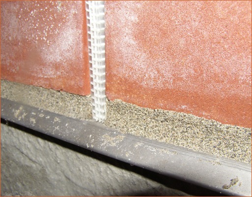
Flashing installations differ from type of material and backup wall condition. A copper flashing laid into the bed joint of a CMU backup wall is ideal, as its termination in the wall holds it in place and makes moisture finding its way behind the flashing from the top impossible. This type of installation never should be performed with a synthetic flashing without checking with the manufacturer, however, since the acids in mortar mixes actually may start to break the membrane down in the joint. Synthetic membranes should always be vertically terminated with a stainless-steel or plastic bar, and then the added steps of cutting the flashing flush with the top edge of the bar and sealing it with a compatible sealant or mastic. It’s a good idea to seal off the fasteners used with the bar as well, as they have a direct route to the backside of the flashing. The flashing height should be consistent with the anticipated height of excess mortar collecting on top of it. Rule of thumb was generally eight inches, but with the wide use of 10-inch mortar collection grids, that height must be expanded to a minimum of 16 inches to assure the excess mortar stays below the top of the flashing material.
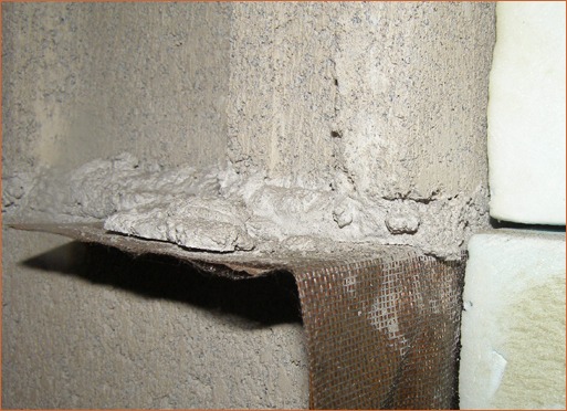
One of the most important details of the flashing installation is located on the outside of the wall. Some projects call for the flashing simply to be cut flush with the wall face after it has been completed. This most certainly will lead to a moisture-related problem over time. As water is carried to this edge, or rain is driven to it, you will see a capillary effect, where water is brought back into the wall underneath and behind the flashing materials. It is so important to have the flashing carry away from the wall face, as noted by the BIA and many other organizations. With a metal flashing, this can be accomplished by extending the flashing an inch or so from the face of the wall and turning it down to form a drip edge, though the aesthetic result is often less than desirable. With all flashing types, the better option is to use a premade drip edge, which has a greater uniformity and more options in its visual appeal. A drip edge also must be properly detailed. It should extend into the bricks a minimum of three inches, with the flashing material lapping over it completely, and sealed with the appropriate mastic. I urge caution when using metal drip edges with asphalt-based peel-and-stick flashings, however, as they tend to carry heat to the asphalt, making it soften and leach more quickly.
So where do flashings need to go? The answer is really quite simple: anywhere there is a horizontal interruption between the veneer and the backup. Most commonly, this occurs at the base of the wall, heads and sills, lintels, shelf angles, and the tops of parapet walls. Parapets are of particular importance, as their copings lay horizontally. Parapets finished with coping stones require maintenance, as mortar joints or sealants eventually will degrade in this orientation. As the joints open up, excessive water will be allowed to pass into the wall. Therefore, I always suggest a heavier, metallic flashing in a smooth profile be placed under the coping materials, or used as the coping itself. A 26-gauge stainless or heavy copper weighing 20 ounces per square foot would be an appropriate choice. In this condition, the metal sections should be soldered in lieu of using a mastic, assuring a strong bond between sections.
A drainage wall system requires only one of these components to be missing for it to fail. Opportunities for failure and culprits of aesthetic or structural issues later on include punctured flashing; an improperly set termination bar; an unsealed drip edge; obstructed weeps; or a missed lap joint. The worst part is that usually, by the time we recognize there’s an issue, it is too late. Closed walls aren’t reopened easily, as the expense is extraordinary. And what’s discouraging is that these are simple details, things we’ve read about or seen in practice for years. But the speed at which we build today can make the most meticulous of masons overlook small pieces of workmanship that have a tremendous impact on the aesthetic appeal and strength of the structure, as well as the health of its occupants.