Brick Veneer
Words: Steven Judd
Words and Figures: Steven Judd
Photo: apugach
There are many assemblies that utilize face brick as the weather barrier: brick veneer over wood stud framing (BV/WS), brick veneer over steel stud framing (BV/SS), or, generically, brick veneer over stud framing (BV/SF), and more inclusively, brick veneer over any substrate wall (BV/SW). Brick veneer can also be applied over concrete walls or over other masonry, like CMU. It doesn’t have to be limited to the cladding over stud framing.
Brick veneer has many significant advantages for use as a durable, tough, non-combustible, long-lasting wall surface. Two of those advantages are its ability to manage water and its ability to enhance the resistance to heat flow through the wall (reduce energy demand).
Water Management
In many design arenas, BV/SW systems are considered to be the “perfect wall” system because of their high performance in managing the exterior environment and keeping the interior of buildings protected. The three critical constituents in this “perfect wall system” are 1) the brick weather barrier, 2) the air cavity, and 3) the water-resistive barrier (WRB). Obviously, the backing wall is also important as it adds restraint and stability to the brick veneer, and the flashings and weeps/vents create a protected pathway to expel water. The wall assembly effectively blocks wind and rain and allows for drainage of any water that may penetrate the weather barrier surface while keeping the substrate wall system dry. Of course, the “perfect wall” performance assumes the design, detailing, materials, and installation are of appropriately high quality.
RAiNA (Rainscreen Association in North America) has officially recognized BV/SW as a true rainscreen system. Interestingly, the term “rainscreen” does not currently exist in any code language. According to RAiNA, a rainscreen is “an assembly applied to an exterior wall which consists of, at minimum, an outer layer, an inner layer, and a cavity between them sufficient for the passive removal of liquid water and water vapor.” The cavity which allows the passive removal of liquid water and water vapor is called a drainage cavity, which is defined as the “space in an enclosure wall assembly between the cladding and the water-resistive barrier that provides a passive means of directing liquid water to the exterior.”
Further to this discussion RAiNA has also included two other terms that relate directly to BV/SW: Vented (cavity) and Ventilated (cavity). “Vented” is defined as “Limited passive exchange of air between the cavity and exterior through openings.” “Ventilated” is defined as “Passive exchange of air between the cavity and exterior through multiple openings that facilitate uniform airflow.” The common differentiation between “vented” and “ventilated” is that a vented BV/SW wall has openings that double as weeps and vents (weep/vents), commonly made of channeled plastic inserts, at the base of the wall or directly above through-wall flashings at other locations, whereas a ventilated BV/SW wall has weep/vents at the base of the wall as with vented systems PLUS vents near the top of the wall or wall segment, or just under through-wall flashings that occur at upper levels. Weeps and vents can also be created by open head joints, but channeled elements are preferred to help prevent bugs from getting into the wall cavity.
 Figure 1: Weep/Vents
It is important to note that cotton duck or cotton rope used as weeps if left in place, neither allows adequate removal (free drainage) of water nor does it allow the exchange of air in the cavity. If left in place, the cotton rope can calcify and not allow any water to drain at all. At best, if left in place, any accumulation of water in the cavity can take days or weeks or longer to drain, one drip at a time. Water that penetrates the veneer should have an uninterrupted, free-flowing water pathway back to the exterior of the wall. To facilitate the free drainage of water, open weave mesh elements produced by various manufacturers, placed at the base of the wall or at shelf angles and lintels, help catch mortar droppings from obstructing the entrance to the weeps.
Energy Management
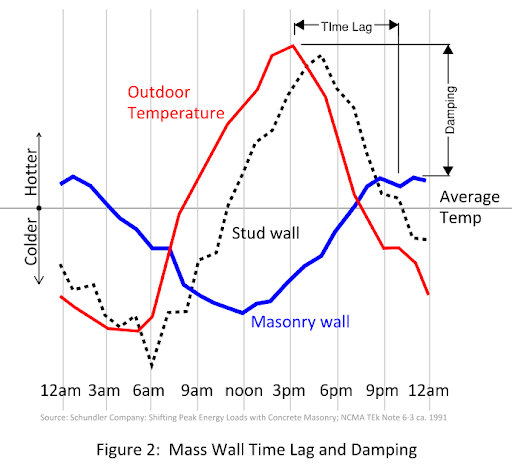
The National Brick Research Center (affiliated with Clemson University) presented a paper at the 13th North American Masonry Conference, held in 2019, based on findings generated via research of hot-box testing of brick veneer walls that conclusively dispelled the myth that a vented or ventilated veneer has no thermal or energy-savings value to the enclosure wall. The research paper clearly concludes that a brick veneer rainscreen system, whether vented or ventilated, effectively acts as a mass wall (meeting the code required minimum heat capacity requirements) tempering the air in the wall cavity both delaying and reducing the heat gain and heat loss of the substrate wall. The brick veneer acts like an energy storage element, regulating the amount of heat or cold that affects the backing wall. The mass of the brick veneer takes time to heat up and takes time to cool down, plus it has its own insulating effect - the temperature of the back face of the brick veneer is generally always lower than the temperature of the exterior face due to the daily cyclic ambient air temperature swings. See Figure 2. The brick veneer, along with the air cavity, makes exterior insulation and integral wall insulation much more efficient, which means less insulation can be used, which reduces the cost of the wall. According to ASHRAE 90.1Energy Standards for Buildings except Low-Rise Residential Buildings, mass walls require less insulation across all climate zones as compared to other wall systems. Bottom line: brick veneer reduces the energy demand of enclosed, tempered, spaces.
Code Changes
The Masonry Society (TMS) recently published their latest edition of “Building Code Requirements and Specification for Masonry Structures''; TMS 402/602-22. TMS 402 is the Building Code Requirements document, while TMS 602 is the Specification document. In this latest edition of TMS 402 the veneer chapter (chapter 13; at 27 pages [was chapter 12; at 12 pages previously]) was considered a complete rewrite rather than a revision. A lot was changed, but much remained unchanged.
The following is a list of some of the notable changes to unreinforced masonry veneers as proffered by the recent TMS 402-22 code update:
1. The code defines maximum limits on the loads that can be applied to the veneer for things directly attached to and supported by the veneer: 20 lbs, and 180-in-lb moment, on any 5 ft x 5 ft area; maximum 12” projection from the face of veneer.
2. Prescriptively designed anchored veneer shall have a maximum specified weight of 50 psf [previously 40 psf limit for veneer supported on wood construction], a maximum specified height of 16 in., and a maximum specified thickness of 5 in.
3. General prescriptive anchored veneer tie requirements have been tabularized which define the veneer tie type, the maximum specified cavity width (generally 1 in, 4in., or 6 in – see item #2 [previously 1 in, 4-5/8 in., and 6-5/8 in.]), and miscellaneous other restrictions or requirements (like maximum veneer height)
4. The specified cavity width shall be from the face of the backing (framing where it exists) to the inside face of the veneer. The specified cavity width shall be permitted to be from the face of sheathing to the inside face of the veneer if: 1) the bearing stress of the veneer tie on the sheathing from allowable stress level loads is less than the allowable bearing stress of the sheathing (Sheathing having an allowable bearing stress of 100 psi is deemed to comply), or if, 2) the veneer ties penetrate the sheathing and directly contact the framing and have a minimum allowable compression capacity of 200 lbs.
5. Pullout resistance of fasteners shall have a minimum design capacity of 335 lbs or an allowable load of 200 lbs.
6. The design method for anchored veneer has changed to a 3-tier designation based on the veneer design wind pressures (pveneer ≤ 50 psf, 50 < pveneer ≤ 75 psf, and, pveneer > 75 psf), and divide by two seismic categories (Seismic design category A, B, and C, and, Seismic Design Category D and higher). See Figure X
7. New table for maximum deflection limits of backing systems to provide out of plane stability based on hb /tsp ratios from 67 to 167; Stiffness ranges of hb /240 to hb /600 for wind, and ranges of hb /100 to hb /250 for seismic. (hb = unsupported height of backing (Wall); tsp = specified thickness of veneer). [Previously no specified deflection limit other than to maintain stability]
8. Tabularized prescriptive designed anchored veneer tie spacings have been added for “Basic” and “Enhanced” conditions. See Figure 3.
9. Deemed to comply with veneer tie strength and stiffness, tables have been added for use with engineered veneer designs.
10. New testing criteria for strength and stiffness of veneer ties.
 Figure 3: Design Methods for Anchored Veneer
11. Out of plane deflection limits of the backing for adhered veneer shall be limited to hb/360 under application of 0.42 times the strength level wind load, and hb/150 under application of strength level seismic load.
12. New tables added for fasteners for various weights and various cavity widths of adhered veneer.
13. Prescriptive design of adhered veneer units must use polymer-modified setting mortar (also called adhesive mortar, or bond-coat mortar) compliant with ANSI A118.4 or A118.15 [current code allows Type S mortar].
14. Adhered veneer units can weigh up to 30 psf. [currently the limit is 15 psf].
15. The assembly weight of prescriptively designed adhered veneer assembly shall not exceed a specified weight of 50 psf. The assembly weight shall include the weight of the units, setting bed mortar, scratch coat, lath, and other materials attached to the backing, where present.
16. Prescriptive design of adhered veneer no longer has a 36” face dimension limit (but retains the 720 in2 area limitation). However, units with a surface area greater than 360 in2 shall have an installation procedure approved by a licensed design professional.
17. Prescriptive designed adhered veneer masonry is limited to a height of 60 feet “above grade plane”. (There was no previous height restriction)
Brick veneer has been shown to be a very effective weather barrier and protection against the elements and an effective material to embrace and leverage the possible energy savings and reduce heating and cooling costs. The recent code changes, some of which are outlined above, will improve even further the design and function of the system known to be the “perfect wall system.”