The discussion of Control Joints should begin with a correct definition of the term. Control joints in masonry are vertical weak planes intentionally built or cut into masonry to control where cracking occurs. Control joints should be installed in any masonry assembly that expected to experience net shrinkage over time.
Usually, we think of control joints in concrete masonry (CMU). However, other masonry products that are portland cement based also shrink over time and should have control joints. For example, precast concrete and cast stone products shrink over time, as well.
Since cementitious masonry products shrink over time, they WILL crack. There are two primary means of controlling where (and how wide) this cracking is: control joints and horizontal reinforcing. Usually, we use a combination of reinforcing and control joints to force concrete masonry to crack at the control joints.
Since it is typically desirable to both hide this cracking and prevent moisture from passing through control joint cracks, most control joints are detailed with joint sealant (caulk) that is flexible enough to stretch and remain water-tight as the control joint cracks and widens.
Unlike expansion joints, it is not necessary to keep control joints free of mortar or debris for them to be functional, since they are designed only to open, not to be compressed. However, leaving out mortar at control joints is good practice in order to ensure that the movement occurs at this joint. If control joints are full of high cement-content mortar, it is possible that cracking could occur through the adjacent unit, rather than within the mortar, since the mortar may actually be stronger than the adjacent unit.
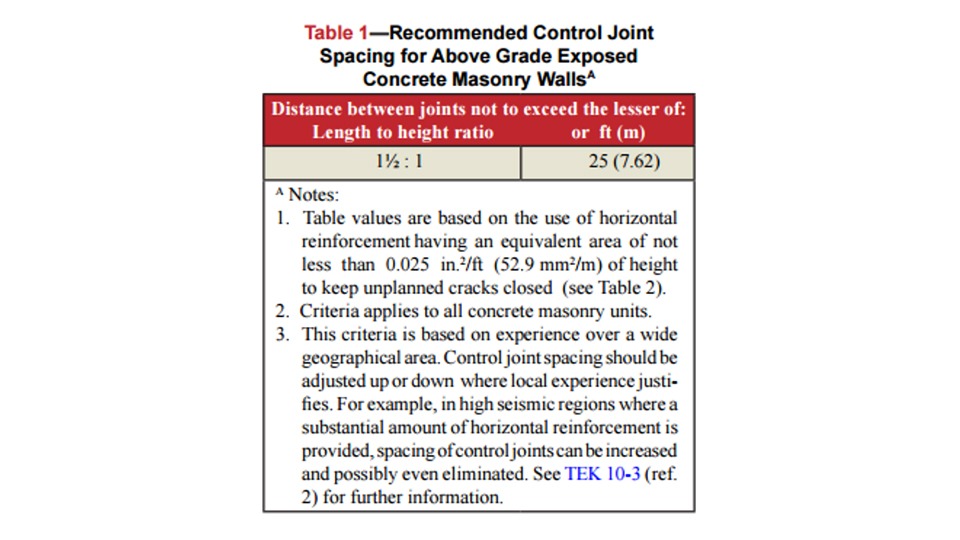 Figure 1. Table 1 from NCMA TEK Note 10-2C describing recommended control joint spacing for typical concrete block masonry assemblies.
As mentioned in the expansion joints discussion, the design of control joint spacing and location is the responsibility of the Designer. Guidance for spacing and location of control joints can be found in the National Concrete Masonry Association (NCMA) TEK Note 10-02C, Control Joints for Concrete Masonry Walls- Empirical Method (2010). Like expansion joints, the primary number to remember is 25 feet (Figure 1).
However, the industry standard also recommends a limit on the aspect ratio (length between joints to height ratio) of 1 ½ to 1. This aspect ratio requirement controls for walls under about 17 feet tall. Note that the NCMA recommendations are designed for concrete masonry walls with a minimum of 0.025 square inches of steel joint reinforcing (ladder reinforcing) per foot of wall height. This is most commonly provided by installing 9 gauge ladder reinforcing at 16 inches on center vertically in a wall. However, this horizontal reinforcing can also be provided using bond beams.

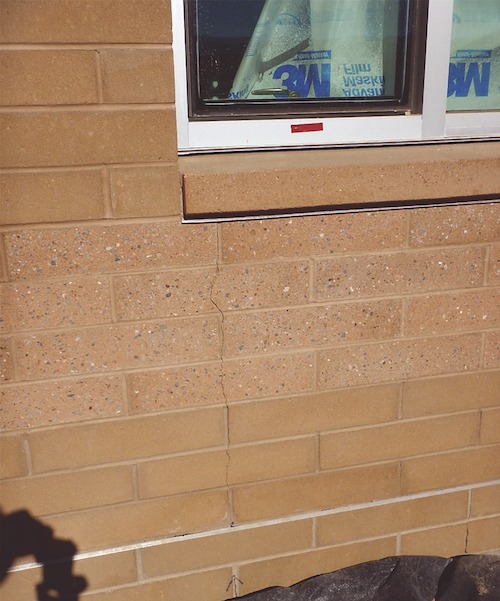
Figure 2. View of shrinkage cracking in a concrete brick veneer beneath a window corner.
If adequate control joints do not provide an intentional weak plane to control where cracks occur, shrinkage cracks will generally find their own weak points in the wall. This typically occurs adjacent to window and door openings since the amount of masonry is reduced at these openings (Figure 2). Windows and doors serve almost like perforations in a sheet of paper being ripped apart. Therefore, it make sense to locate control joints at these locations where cracks would naturally tend to form.
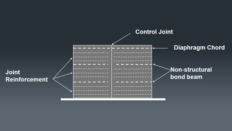 Figure 3. Schematic drawing showing bed joint reinforcement and non-structural bond beam reinforcing to be discontinuous at control joints.
There are several common mistakes observed in modern control joint installation. First, it is sometimes observed that bed joint reinforcing is installed continuously across a control joint. This reinforcing does not allow the control joint to open easily and can make the joint non-functional. In fact, extra horizontal reinforcing can be used to extend control joint spacing or prevent cracking at natural weak points in walls.
All joint reinforcing and non-structural bond beams (such as bond beams used for temporary wind bracing or shrinkage control only) should be discontinuous at every control joint (Figure 3). Structural bond beams, such as diaphragm chords at the roof line should be continuous across control joints. If you don’t know whether or not a bond beam should be continuous across a control joint, be sure to get clarification from the Design Engineer in writing.
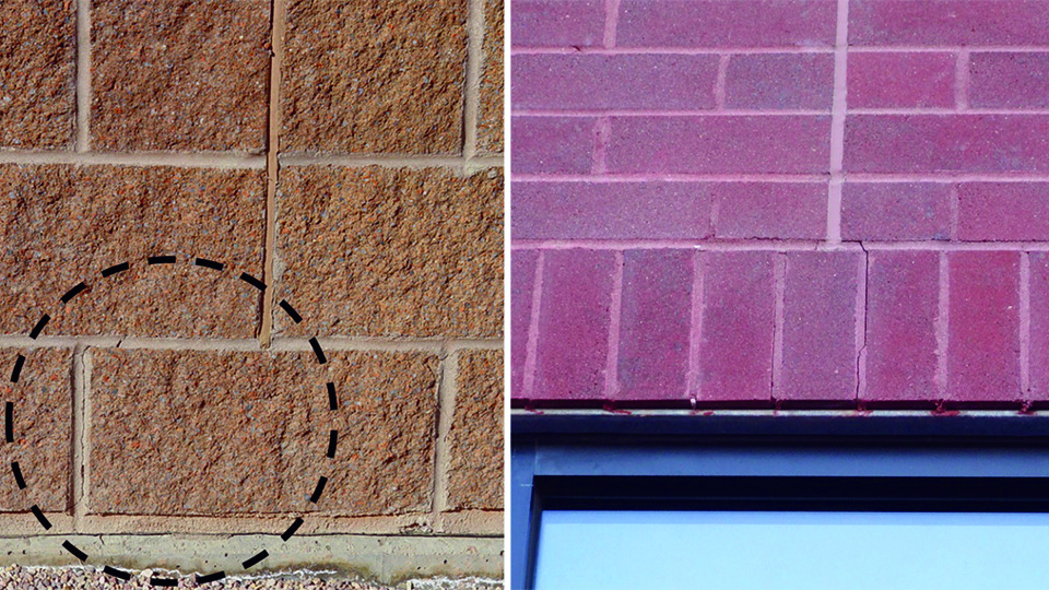 Figure 4. (Left) View of a control joint in a split-face concrete block wall that stops 1 course above the base of the wall. (Right) View of a control joint in a concrete brick veneer where the control joint stops at a soldier course above a window lintel, leading to cracking at the soldier course.
Another common control joint problem is stopping control joints short of the bottom of a wall or the top of a window/door opening (Figure 4). Often, control joints are stopped short of the bottoms of walls due to below-grade waterproofing concerns. However, if the portion of the wall below the joint cracks anyway, the waterproofing conditions are worse than continuing the joint below grade.
A better approach is to install waterstop (and joint sealant) at the joint below grade and continue the joint to the base of the wall. Joints are often stopped short at soldier courses above windows and doors since the head (vertical) joints do not align. Better practice is to continue the control joint, even if it must include a horizontal jog. Bed (horizontal) joints cannot be left free of mortar, but the mortar in bed joints can be raked back from the surface to permit joint sealant (caulk) installation.
 Figure 5. View of concrete brick veneer showing control joint locations (indicated with green lines) and shrinkage cracking (indicated with dashed yellow line). This veneer did not contain bed joint reinforcing.
Another common control joint error is the omission of bed joint reinforcing and/or control joints in concrete masonry veneer (Figure 5). Even though concrete masonry veneer is not structural, it almost always must have bed joint reinforcing and control joints to control shrinkage cracking.
Occasionally, concrete brick veneer is substituted for clay brick material during the construction process, and the design documents and details do not address the need for bed joint reinforcing. However, block veneer is susceptible to the same shrinkage cracking behavior as load-bearing concrete block, and it requires the same types of reinforcing and control joint installations.
Words and Photos Courtesy of the MCAA