INTRO TO MASONRY FLASHING
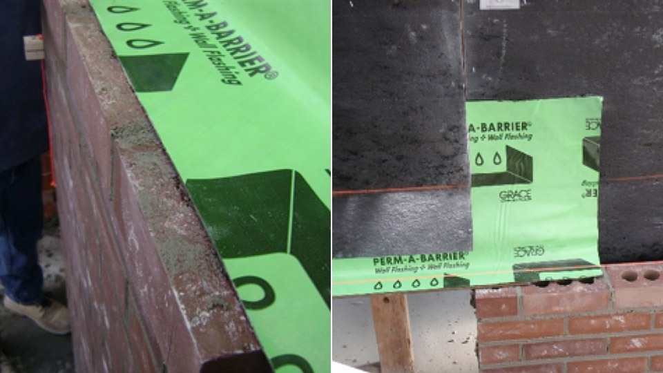
Mason contractors are usually directed to install flashing with their masonry product. Flashing acts as a barrier, which redirects moisture away from building interiors and back toward the exterior of the wall. Common flashing materials include synthetic membranes (peel and stick) and metals, such as copper and stainless steel. The material that is used will directly affect the expected lifespan of the flashing, especially where flashings are exposed to sunlight or weathering.
Flashing needs to be accompanied by a weep mechanism to allow moisture to exit the wall, often in the form of weep holes or head joint vents at horizontal terminations. The weeps should be placed directly above the flashing and extend all the way to masonry drainage plane. In order for moisture to reach and exit the weeps, both the weeps themselves and the drainage cavity adjacent to the weeps should be kept clear of mortar clogging. Installation of vents at the top of a drainage cavity aids air flow behind the masonry, decreasing drying time and reducing the risk of efflorescence.
Drip edges force moisture at flashings away from the face of the wall and reduce the amount of moisture that can bypass or be re-absorbed beneath a flashing. Flashing materials, such as asphalt can soften and melt onto the face of masonry with UV or high heat exposure. These flashing types must be cut or held back the wall face, and a drip edge can be used to direct moisture away from the wall face. The drip edge must be made of a material that is not sensitive to UV exposure and won’t corrode.
Flashing is required for veneer in cavity wall systems, but it is also required for structural masonry. The building code requires that flashing be designed and detailed, so if project drawings don’t show where flashing is supposed to be installed, be sure to check with the designer (in writing). Some locations where flashing is likely to be needed are:
- Base of wall (usually at each story)
- Lintels above openings
- Under sills, caps, and rowlocks
- Beam pockets
- Penetrations (plumbing, electrical, ventilation)
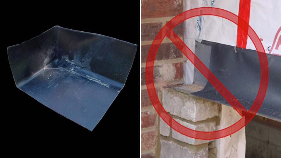
Workmanship and detailing are important to the success of a masonry flashing system. Seams between separate flashing pieces need to be lapped and properly sealed using products approved by the flashing manufacturer. End dams are often required at flashing terminations such as at the edges of lintels and inside corners. The use of manufactured inside and outside corner flashings can simplify flashing installation and reduce the number of seams and potential leak locations in a masonry flashing system.
COMMON ISSUES WITH FLASHING
Figure 2. Protruding membrane flashing with a gap at a lap location.
Many of the biggest dilemmas (and lawsuits) involving masonry construction have nothing to do with brick, block, stone, mortar, or grout. When masonry leaks and fingers start pointing, there are usually lots of eyes that look immediately to flashing within the masonry. There is good reason for this attention. Flashing is where we intentionally collect and divert moisture within a wall system. Therefore, it is also one of the most likely places to experience moisture infiltration when things go wrong.
Fortunately, there are increasingly abundant resources that provide guidance on flashing installation. And many leaks can be eluded by avoiding just a few common issues. Let’s look at a few:
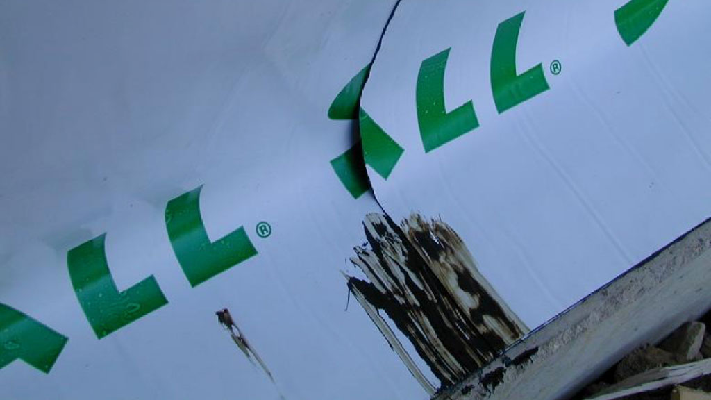
Figure 3. Lap in membrane flashing that has tenting and an associated gap at the back surface.
LAPS IN ADHERED FLASHING
One of the most common moisture infiltration locations in masonry flashing occurs at joints or laps in the flashing. Self-adhered flashing can be awkward to work with, and it is not uncommon to end up with gaps between pieces or tenting and incomplete contact. Water sitting on this flashing often finds its way into these imperfections and can create problems for everyone involved. To reduce problems at laps, institute a careful training and inspection protocol for flashing, including how to seal each lap. Make sure your crews understand that few extra feet of flashing and some butyl sealant are a LOT cheaper than a lawsuit. Don’t forget about laps and terminations at the top edges of your flashing. Make sure that termination bars are installed and sealed in accordance with the manufacturer’s requirements.
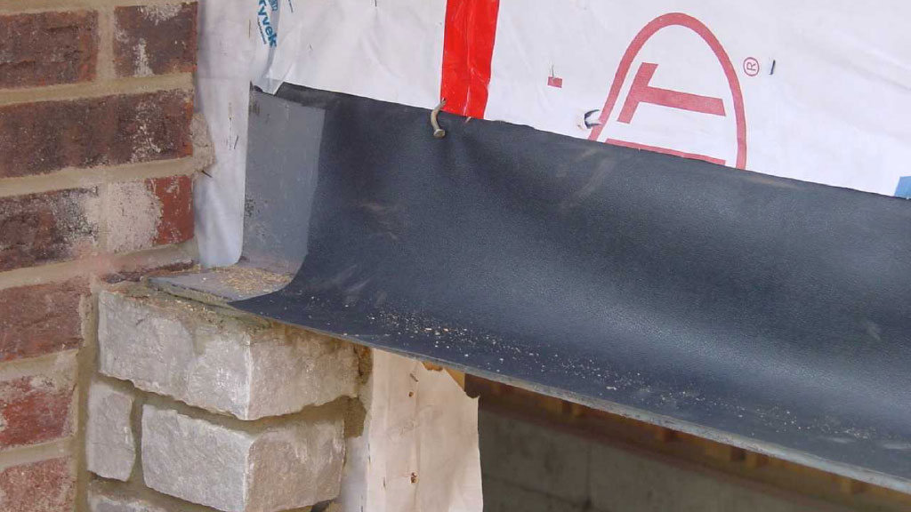
Figure 4. End detail at a lintel where the flashing stops short of the end of the lintel.
END CONDITIONS AND END DAMS
In many masonry applications, flashing installation within the field of the wall is done correctly and efficiently. However, when a lintel or shelf angle terminates at or near an inside or outside corner, things unravel. The flashing approaches that worked in the field of the wall suddenly don’t “fit”, and getting material around corners and into tight spots can be a pain. However, these awkward locations will be some of the first spots that a plaintiff’s expert will open up to examine your workmanship. Therefore, pay special attention to all inside and outside corner conditions, and use prefabricated corner boots whenever possible. Again, the tens of dollars you spend now could save you thousands of dollars later.
CLOGGED DRAINAGE CAVITIES
Although there have been good mortar dropping control systems for masonry on the market for many years now, clogged cavities around flashing continue to be problematic on some buildings. One of the common issues is a tight drainage cavity due to the installation of external insulation. If your project specifies a cavity less than 2” wide, send the design team a letter with a copy of BIA Technical Note 21 and ensure them that there will be mortar bridging with a narrow cavity design. Also, try to get as many weep vents as you can at your flashing. Air flow through these vents helps dry out the masonry in addition to water drainage though the weeps. Air does not flow well through rope wicks, by the way…
DRIP EDGES
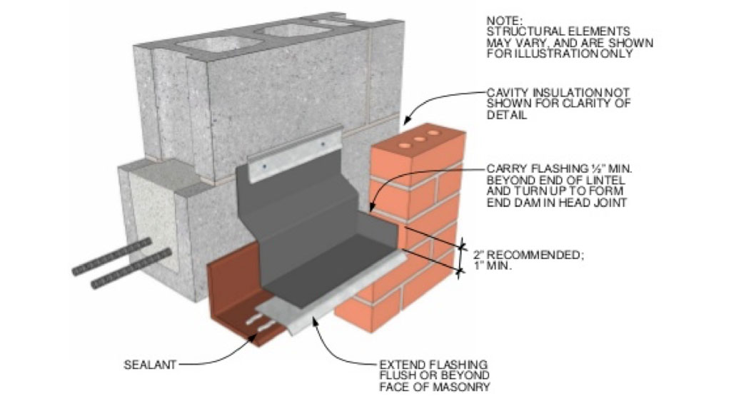
Water is amazingly creative and stubborn when it is flowing through masonry. Whenever possible, use drip edges to get as much water as possible out of the masonry and off of the masonry surface. The Building Codes are edging toward drip edge requirements, so encourage your design team to bite the bullet and put them in. They really don’t look bad. I promise!
Figure 5. From the Masonry Systems Guide by the International Masonry Institute.
If there are questions about the performance of a masonry drainage and flashing system, it can be evaluated using ASTM C1715, “Standard Test Method for Evaluation of Water Leakage Performance of Masonry Wall Drainage Systems.” The test involves introducing a controlled flow of water directly into the cavity, and directly observing the moisture path as the water interacts with flashing and weeps.
Words: Mason Contractors Association of America
Photos: Mason Contractors Association of America
Sidebar
Air Barriers + Through Wall Flashing = A Better Barrier System
There is a misconception that air barriers and through wall flashings are one and the same. That is not always the case. Air barriers should be installed along with through-wall flashings as a system, not as the only waterproofing defense. “The intent of thru-wall flashing is to extend ‘through the wall’,” Keith Lolley, the President of Advanced Building Products Inc. clarifies. In order to extend through the wall properly a few things need to be taken into consideration while choosing the flashing. The through-wall flashing should span the airspace or cavity while holding its shape without a structural member underneath for support. As walls heat up, some membranes don’t hold their shape and can actually become deformed in the cavity, this allows moisture to remain trapped instead of proper evacuation with the air barrier installed. Ensure the flashing UV resistant and compatible with the air barrier products being installed. Another consideration to have in mind is life expectancy of the flashing used.
Answering the question of the life expectancy of the building will determine the type of flashing used on the project according to Lolley. His recommendation for the best through wall flashing are either laminated copper or stainless steel flashings, since they both have compatibility and longevity. Buildings with high-end flashings have a minor fraction of the total construction cost of the building. If they’re installed properly, they’ll never have to be replaced, Lolley contends. If a less expensive flashing product is chosen, it is suggested to research the life expectancy. However be sure to factor in the replacement costs if the warranty doesn’t match the life expectancy. This will reduce the number of options available for the project right away, which will make the selection process easier for the architect.
