Masonry Anchors and Ties by the Code
Words: Dan Kamys
Anchors, Connectors and Fasteners
By Paul Curtis
Masonry anchors and ties are to be designed and installed based on the Building Code Requirements and Specification for Masonry Structures (TMS 402-11/ACI 530-11/ASCE 5-11). This article will examine code compliant anchors for both masonry walls and for brick veneers.
Masonry walls
Masonry walls tied to concrete columns:
Typically dovetail anchor slots are cast into the concrete column, and anchors are installed into the masonry walls. Channel Slot Systems or various two-piece systems can be used on columns without dovetail slots.

Masonry walls tied to steel beams:
Various anchors are available depending on the direction of the beams.
Masonry to masonry:
The code requires that masonry walls consisting of two or more wythes separated by an air space must be connected by wall ties. Nine-gage wire ties are spaced one anchor every 2.67 square feet, and 3/16-inch wire ties are spaced one anchor every 4.5 square feet. The maximum spacing is 36 inches horizontally and 24 inches vertically. Multiwythe walls designed for composite action and not bonded by headers typically are connected with rectangular ties, Z-Type ties or wire reinforcement. Z-Type wire ties must have the cells grouted solid. These anchors can be used in non-composite walls along with adjustable anchors.
 4-Wire Joint Reinforcement
The adjustable anchor requirements differ in that the maximum horizontal spacing is reduced to one anchor every 1.77 square feet, and the vertical spacing to a maximum of 16 inches. The maximum misalignment of bed joints is 1.25 inch, the clearance between the connecting parts cannot exceed 1/16 inch and the pintle ties must be 3/16 inch diameter.
Truss-type wall reinforcement is not allowed in non-composite walls, because it restricts in-plane differential movement between wythes.
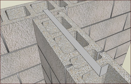
Intersecting walls:
Intersecting walls require a U or Z Type Rigid Steel anchor ?? inch thick x 1.5 inch wide x 24 inches o.d., with two-inch bends. These are to be placed a maximum of 48 inches, and all cells above and below the anchor are to be grouted.
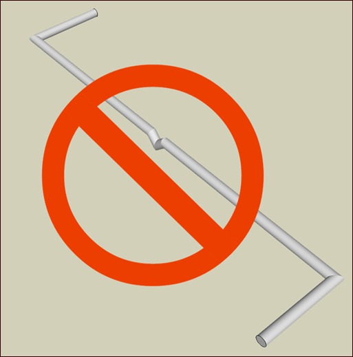
Many years ago, some masonry wall ties incorporated a drip bend in the middle of the cavity to allow moisture to migrate to the center and drip down into the cavity. The drip greatly reduced the anchor strength so any and all anchors with drips have been eliminated for use by the code.
The code also limits the cavity to 4.5 inches to assure adequate performance. Ties in larger cavities must be designed to resist loads, based on rational analysis taking into account buckling, tension, pullout and load distribution.
Brick veneers
The backing system of exterior veneer must be designed and detailed to resist water penetration. The exterior sheathing must be covered with a water-resistant membrane, unless the sheathing is water resistant and the joints are sealed.
Flashing and weep systems in exterior veneer must resist water penetration into the building interior. Weepholes must be at least 3/16-inch in diameter and spaced less than 33 inches on center.
Anchor finishes for masonry and veneer walls:
Anchors in all exterior walls and any interior walls exposed to a mean relative humidity exceeding 75 percent must be Hotdip Galvanized After Fabrication or Stainless Steel. For all other cases, anchors may be Mill Galvanized, Hotdip Galvanized After Fabrication or Stainless Steel.
Placement in veneer:
Both solid and hollow masonry units should have the anchors embedded a minimum of 1.5 inches from the interior veneer face and should have at least 5/8-inch mortar or grout cover to the outside face.
The code allowances below are for veneers that are a maximum of 4.5 inches from the backup and the inside of the veneer. The minimum airspace allowed is one inch.
There are five types of anchors noted in the code: corrugated sheet metal anchors, sheet metal anchors, wire anchors, joint reinforcement, and adjustable anchors.
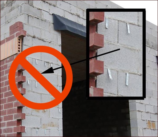
1. Corrugated sheet metal anchors:
These are to be a minimum size of 22 gage x 7/8-inch-wide with corrugation wavelength between 0.3 to 0.5 inch, and an amplitude of 0.06 to 0.1 inch. These anchors primarily are used in residential brick veneers and are only allowed with wood-frame backups and a maximum airspace of one inch. They are to be installed with screws or ring-shanked nails. The fastener must be located within ?? inch of the 90-degree bend in the anchor.
2. Sheet metal anchors:
These are more commonly seen in commercial applications. Sheet metal anchors have a minimum thickness of 16 gage and a minimum width of 7/8 inch. Unlike the corrugated sheet metal anchors, these anchors are pre-bent in the factory and provide a much greater compressive strength. The Sheet metal anchors can be used only with wood-frame backups.

3. Wire anchors:
These anchors are used in both residential and commercial applications. They must be a minimum of nine-gage and have a two-inch minimum bent end in the veneer. They can be used with wood and masonry backup walls, but not with a concrete backup wall.
4. Joint reinforcement:
Ladder and tab type are both permitted. The minimum wire size is nine-gage with the cross-wires to be a maximum of 16 inches on center. Provide minimum six-inch lap splices, and ensure that all ends of the longitudinal wires are embedded in mortar at laps. Joint reinforcement should conform to ASTM A951.
5. Adjustable anchors:
These anchors are permitted with all backups. Adjustable anchors are the only types allowed with steel stud backup and concrete backup, due to deflection of the two walls. As with the masonry walls, veneer adjustable anchors maximum misalignment of bed joints is 1.25 inch, the clearance between the connecting parts cannot exceed 1/16 inch, and wire ties must be nine-gage minimum with a strap or screw and 3/16 inch when both parts are wire. Single pintle wire ties are permitted with the latest 2011 version of the code.
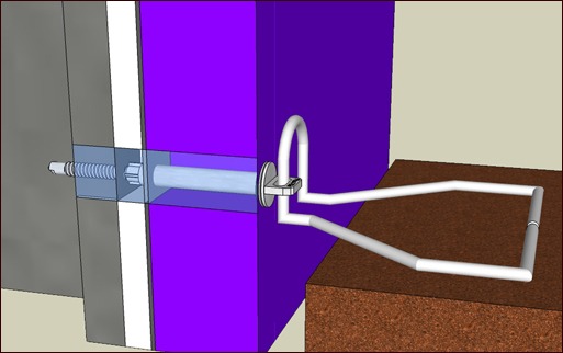
 Barrel Screw type for transfer of loads back to structure
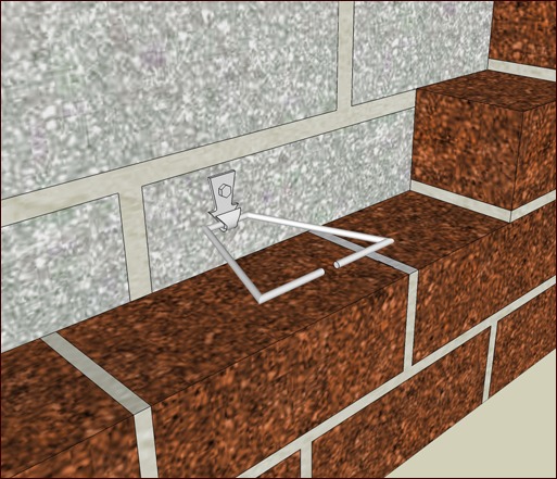
 Plate Type with Triangle
Brick veneer anchor spacing:
For adjustable two-piece anchors, nine-gage wire anchors and 22-gage corrugated sheet-metal anchors; provide one anchor for each 2.67 square feet of wall area. For all other anchors, provide one anchor for each 3.5 square feet of wall area. Space anchors at a maximum of 32 inches horizontally and 25 inches vertically. Additional anchors should be placed around openings larger than 16 inches in either dimension. Space them around the opening perimeter at a maximum of three feet on center and within 12 inches of openings.

Mortar bed joint thickness must be at least twice the thickness of the embedded anchor (3/16-inch wire tie requires a 3/8-inch minimum joint.)
Correctly specifying, detailing and installing the proper masonry anchoring system for your project will help insure a trouble-free structure for many years to come.
Correctly specifying, detailing and installing the proper masonry anchoring system for your project will help insure a trouble-free structure for many years to come.