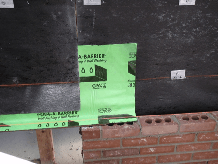
Masonry contractors are usually directed to install flashing with their masonry product. Flashing acts as a barrier which redirects moisture away from building interiors and back toward the exterior of the wall. Common flashing materials include synthetic membranes (peel and stick) and metals, such as copper and stainless steel. The material that is used will directly affect the expected lifespan of the flashing, especially where flashings are exposed to sunlight or weathering.
Flashing needs to be accompanied by a weep mechanism to allow moisture to exit the wall, often in the form of weep holes or head joint vents at horizontal terminations. The weeps should be placed directly above the flashing and extend all the way to masonry drainage plane. In order for moisture to reach and exit the weeps, both the weeps themselves and the drainage cavity adjacent to the weeps should be kept clear of mortar clogging. Installation of vents at the top of a drainage cavity aids air flow behind the masonry, decreasing drying time and reducing the risk of efflorescence.
Drip edges force moisture at flashings away from the face of the wall and reduce the amount of moisture that can bypass or be re-absorbed beneath a flashing. Flashing materials, such as asphalt can soften and melt onto the face of masonry with UV or high heat exposure. These flashing types must be cut or held back the wall face, and a drip edge can be used to direct moisture away from the wall face. The drip edge must be made of a material that is not sensitive to UV exposure and won’t corrode.

Holding flashing back from the wall face can result in entry points for moisture to penetrate the wall.
Flashing is required for veneer in cavity wall systems, but it is also required for structural masonry. The building code requires that flashing be designed and detailed, so if project drawings don’t show where flashing is supposed to be installed, be sure to check with the designer (in writing). Some locations where flashing is likely to be needed are:
- Base of wall (usually at each story)
- Lintels above openings
- Under sills, caps, and rowlocks
- Beam pockets
- Penetrations (plumbing, electrical, ventilation)
Workmanship and detailing are important to the success of a masonry flashing system. Seams between separate flashing pieces need to be lapped and properly sealed using products approved by the flashing manufacturer. End dams are often required at flashing terminations such as at the edges of lintels and inside corners. The use of manufactured inside and outside corner flashings can simplify flashing installation and reduce the number of seams and potential leak locations in a masonry flashing system.


Use of end dams at the edges of lintels is recommended. Manufactured corner pieces are available for this purpose.
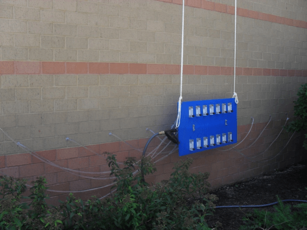
If there are questions about the performance of a masonry drainage and flashing system, it can be evaluated using ASTM C1715, “Standard Test Method for Evaluation of Water Leakage Performance of Masonry Wall Drainage Systems.” The test involves introducing a controlled flow of water directly into the cavity, and directly observing the moisture path as the water interacts with flashing and weeps.
For free information and industry recommended masonry flashing details, see the following resources:
Brick: Brick Industry Association (BIA) Technical Notes on Brick Construction No. 7: Water Penetration Resistance – Design and Detailing.
CMU: National Concrete Masonry Association (NCMA) TEK 19-5A: Flashing Details for Concrete Masonry Walls.
Adhered Manufactured Stone Veneer: Masonry Veneer Manufacturer’s Association (MVMA) Installation Guide and Detailing Options for Compliance with ASTM C1780.
Words: Donald Harvey
Photos: Atkinson-Noland and Masonry Magazine